System components
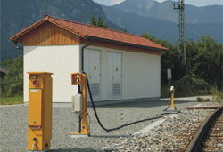
Accessible concrete building
- Type tested
- Accidental arcing security tested
- Reinforced concrete, C35/45 in accordance with DIN 1045-2
- Dispersion coating of exterior walls
- Aluminum pierce-proof door fans and roof hoods for air ventilation
- Maintenance-free doors made of anodized aluminum with panic lock
- Raised floor made of concrete or lockable composite wood plates
- Transformer room with hot-dip galvanized guide rails and track limiter rails, Halfen anchoring system flush-embedded in concrete, separating walls between the transformer rooms, basement oil-proof
- Flat roof or in the style of the local architecture, e.g., gable end
- Cable entries
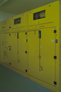
Medium-voltage switchgear
Type-tested with vacuum circuit breaker with steel sheet recess for secondary devices
Three-phase systems
-
36 kV, 50 Hz
- 24 kV, 50 Hz
- 12 kV, 50 Hz
Single-phase systems
- 25 kV, 50 Hz
- 15 kV, 16,7 Hz
- 11 kV, 16,7 Hz
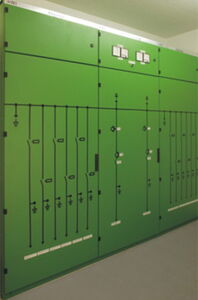
Switchgear for heating outlets
Including:
Switchboard for feeding with 1 or 2 transformers,
Switchboard for 2, 4, or 6 heating outlets with sheet-steel compartment for auxiliary equipment
Three-phase system
- 400 V, 50 Hz
Single-phase systems
- 330 V, 16,7 Hz
- 1000 V, 16,7 Hz, 50 Hz
- 1500 V, 50 Hz

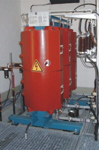
Transformers
Three-phase transformers
Single-phase transformers
Standard configuration:
- Oil-filled transformer
Special transformer models:
- Cast-resin transformer
- Dry-type transformer
With built-on rollers
With monitoring unit
Transformer outputs
Three-phase system 50 Hz
- 315 kVA, 630 kVA, 800 kVA,1250 kVA, 1500 kVA
Single-phase system 25 kV, 50 Hz
- 1250 kVA, 1600 kVA
- Single-phase system 15 kV, 16,7 Hz
- 800 kVA, 1000 kVA, 1250 kVA
- Single-phase system 11 kV, 16,7 Hz
- 630 kVA, 1000 kVA
Special sizes on demand
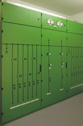
Low-voltage switchgear
- Fully electronic microprocessor control
- Control signal input 230 VAC
- Voltage measuring inputs 100 VAC
- Measuring current inputs 1 AAC
- 15″ touchscreen for data display, queries, and computer operation Evaluation software
- Data logger to store the switching operations and measured values Data memory can be read out via modem
- DCF 77 time synchronization
- Single or double control pillar
- Housing and screws in A2
- Height 1,025mm, 750mm
- Outside-temperature-dependently controlled microprocessor time switch with DCF 77 synchronization
- Freeze-protection mode at exterior temperatures below 1.5°C
- For ground mounting
Optional:
- For wall mounting
- With digital ammeter or voltmeter
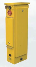
Cable-connection box with predetermined breaking point
- Hot-zinc-dipped post
- With cut-off point
- With monitoring switch
a) One-way pull-off, height 720 mm
b) Both-way pull-off with kink, height 1,080 mm/750 mm For floor mounting
Optional:
- For floor mounting
- For wall mounting
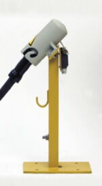
Plug holder with dummy socket
- Hot-zinc-dipped holder
- With monitoring switch
- Height 860mm/750mm
- For ground mounting
Optional:
- For wall mounting
- For mounting on rail pillars
- With cable storage
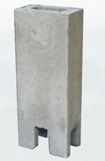
Concrete fundament
For fastening outdoor components
- With screw sockets in A2 steel
- With openings for cable entry on all sides

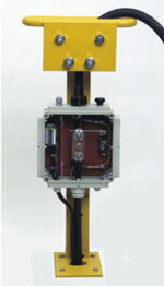
Integrated control pillar
Single control pillar
- Housing and screws in A2
- Height 1,045mm
- Width 200mm
- Integrated predetermined breaking point with turn rollers for both-way pull-off
- With breakaway contact
- With monitoring switch For ground mounting
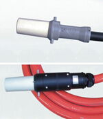
Connecting cable
For feeding energy into the coach socket
- Flexible rubber hose cable, 185/25mm²
- Connection plug, 800 A
- Optional: with pilot contact